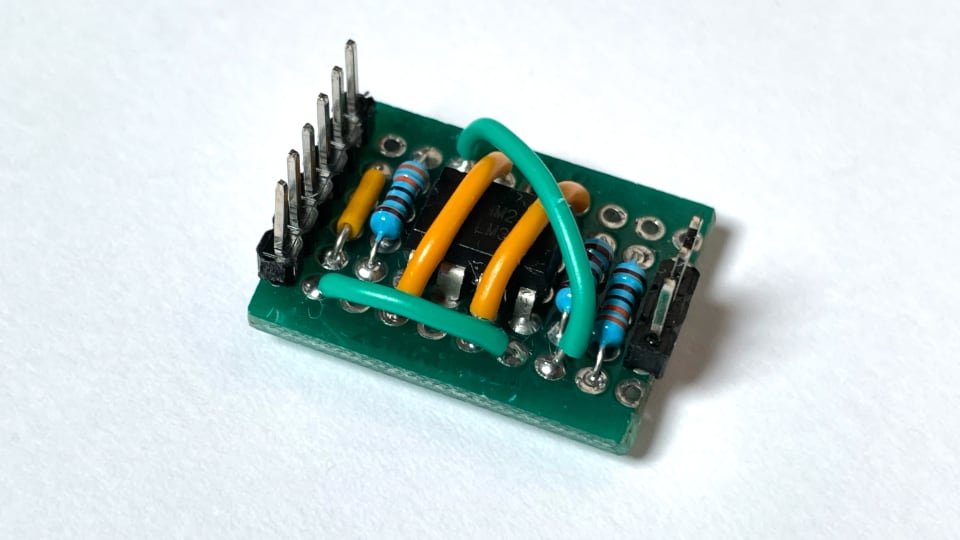
Proto Board for Monitor Mode
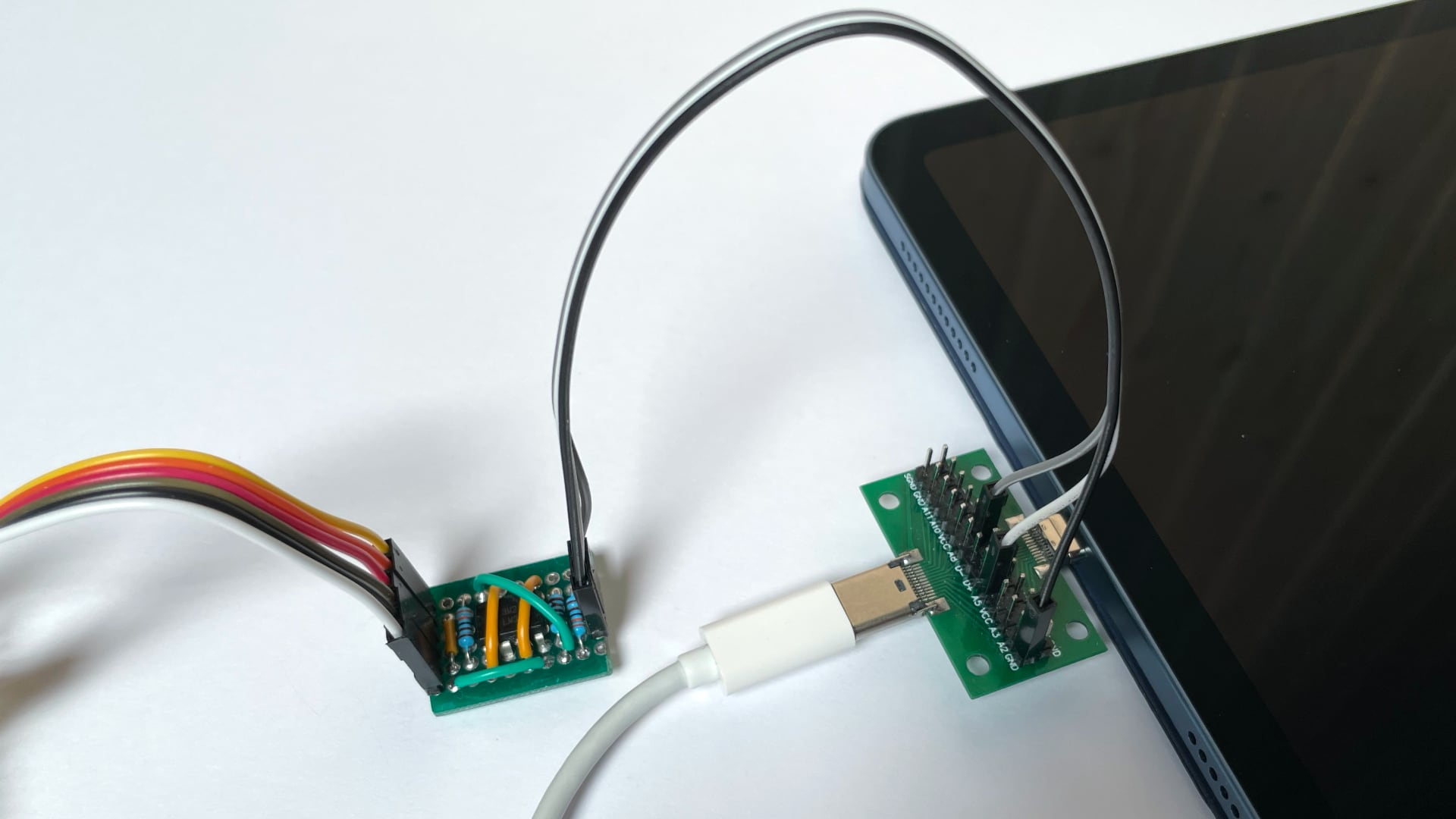
The additional hardware required for several MCUs can easily be implemented on a proto board. The below proto board implements the schematic and adds connectors and headers.


To monitor the USB PD communication, an intermediate plug needs to be connected between the two USB PD devices. The below USB C adaptor board with both a male and a female USB C connector works.
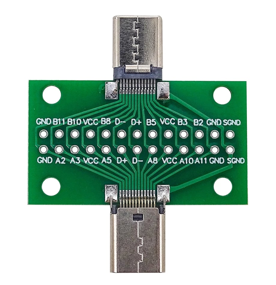
Note that the relevant signals are called A5 (for CC1) and B5 (for CC2). GND must also be connected to the proto board.
| Label | Component | Quantity |
|---|---|---|
| LM393P | Dual comparator with open-collector output | 1 |
| 1K | 1kΩ resistor | 1 |
| 3.3K | 3.3kΩ resistor | 2 |
| – | 6 pin header | 1 |
| – | 3 pin header | 1 |
| – | USB C intermediate adaptor board | 1 |